Qeexo

TRY
BACK TO PRESS

Tree Model Quantization for Embedded Machine Learning Applications

Dr. Leslie J. Schradin, III 28 May 2021

This blog post is a companion to my talk at tinyML Summit 2021. The talk and this blog overlap in some content areas, but each also has unique content that complements the other. Please check out the video if you are interested.

Why Quantization?

For embedded applications, size matters. Compared to CPUs, embedded chips are much more constrained in various ways: in memory, computation ability, and power. Therefore, small models are not just desirable, they are essential. We at Qeexo have asked ourselves: how can we make small, high-performance models? We have dedicated resources to answering this question, and we have made advances in compressing many of our model types. For some of those model types, compression has been achieved through quantization.

For our purposes here, the following is what we mean when we “quantize” a machine learning model:

Change the data types used to encode the trained-model parameters from larger-byte data types to smaller-byte data types, while retaining the behavior of the trained model as much as possible.

By using smaller-byte data types in place of larger-byte data types, the quantized machine learning model will require fewer bytes for its encoding and will therefore be smaller than the original.

Why Tree Models?

In our experience at Qeexo we have found that tree-based models often outperform all other model types when the models are constrained to be small in size (e.g. < 100s KB) or when there is relatively little available data (e.g. < 100,000 training examples). Both of these conditions are often true for machine learning problems targeting embedded devices.

Memory constraints on embedded devices

As stated above, due to the memory constraints on the device the models must be small. For example, the Arduino Nano 33 BLE Sense has 1 MB CPU flash memory and 256 KB SRAM. These resources are shared among all programs running on the device, and the available resources for a machine learning model are going to be significantly smaller than the full amounts. The actual resources available for the machine learning model will vary by use-case, but a reasonable estimate as a starting point is that perhaps half of the resources can be used by the machine learning model.

Available data for embedded machine learning applications

As for the amount of available data, several factors tend to lead to relatively little available data
for machine learning models targeting embedded devices:

  • To train a machine learning model that is to be used on a given embedded platform, the training data must be collected from that platform. Large datasets collected from embedded platforms are not generally available online.
  • The organization that wishes to produce the machine learning model must usually collect the data on its own. This is costly in time and effort.
  • Machine learning applications usually require specialized training data. This means that a data collection effort usually needs to be performed for each problem that is to be solved.

Because tree-based models tend to perform well, and are often the superior model type, under the constraints above, they are well-suited for embedded devices. For this reason, we are interested in using them for our own embedded applications and in offering them as part of our suite of models for use in Qeexo AutoML.

Tree Model Quantization

Encodings of trained tree-based models lead to parameters and data that fall into 3 categories:

  1. Leaf values: these are the values that carry the information about which class or regression value is the prediction for the instance in question during inference.
  2. Feature threshold values at the branch nodes: these values determine how an instance traverses the tree during inference, and eventually which leaf is reached in the end.
  3. The tree structure itself: this is the information encoding how the various nodes of the tree connect to each other.

The first two categories above, leaf values and feature thresholds, provide the possibility for quantization. At Qeexo, we have implemented quantization for these parameter types. While there has been research on and implementations for quantization of neural-network-based models, we aren’t aware of similar research and implementations for tree-based models; we have done our own research and created an implementation for quantization for tree-based models.

Quantization Gains and Costs

Our main gain for quantizing tree-based models: model compression

In our experience, the strongest constraint placed on tree models by embedded chips is the flash size. By quantizing the model, the number of bytes needed to encode the model is smaller. This allows tree-based models to fit on the device that would not have fit without quantization, or in the case of smaller tree-based models, quantizing them leads to more room on the embedded device for other functionality.

The main cost for quantizing tree-based models: loss of model fidelity

Reducing the size of the data types used to encode the trained model parameters leads to some loss of information for those parameters, and this leads to a difference in behavior between the original model and the quantized version. The difference in behavior is often small, but if it is not small enough it can sometimes be made smaller by giving up some compression gains (i.e. increase the size of the quantized data type; in the “Leaf Quantization Example” below, one could use the 2-byte uint16 instead of the 1-byte uint8 as the quantized data type. This would make the quantized model more faithful, but also bigger).

There is another factor that can lead to a reduction in compression gains when quantizing tree-based models: depending on the tree model in question and on the quantization type, it may be necessary to store some of the parameters of the quantization transformation along with the model on-device. This is because in some cases it is necessary to de-quantize one or more quantized parameters during inference to correctly produce predictions or prediction probabilities. Storing these transformation parameters costs bytes on-device, which eats into the compression gains. The number of transformation parameters required depends strongly on the quantization type. For example, when using a simple quantization scheme such as an affine transformation (a shift followed by a rescaling), the leaf quantization transformation parameters are 2 floating-point parameters if all leaf values are quantized together. On the other hand, for feature threshold quantization, each feature used in the model requires a stored transformation, which leads to 2 floating-point parameters per used feature. The former costs very little (a few bytes), and is applicable to any tree implementation with floating-point leaf values or integer leaf values when the values are large enough. The latter can cost many bytes depending on the number of features, and should only be considered for large models where the number of splits per feature across the tree-based model is large enough to absorb the cost of storing the feature threshold quantization parameters.

Leaf Quantization Example

To illustrate the gains and costs of tree model quantization, we’ll consider an example using leaf quantization. For our example, consider a “letter gesture” problem, a benchmark problem we use often at Qeexo. The setup:

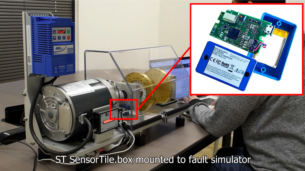
  • Arduino Nano BLE Sense, held in the hand
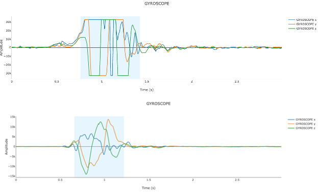
  • Accelerometer and gyroscope sensors active
  • 4 classes of letter gestures, traced out in the air: A, O, S, V
  • 1 class of no gesture
  • Qeexo AutoML accelerometer and gyroscope feature stack used for the features
  • Data after featurization: approximately 300 examples for each letter gesture, and 1500 examples for the no-gesture case
  • Train/test split: approximately 2/3 of the data is used for training, 1/3 as the test set
  • Model: sklearn.ensemble.GradientBoostingClassifier with default parameters (mostly)

The Un-Quantized Model

  • Overall accuracy on the held-out test set: 96.1% (927/965)
  • Confusion matrix:
true/predANOISEOSV
A1330202
NOISE0543000
O009810
S3121950
V800058
  • The model performs pretty well. The most difficult class for the model to classify correctly is ‘S’, which is at times classified as ‘O’
  • Bytes to encode the model and the breakdown into categories:
ValueNumberEncodingBytes
Leaves3595float3214380
Feature Thresholds3095float3212380
Tree Structurevarious uint12884
Total39644

The breakdown in bytes will generally follow this pattern, with the leaves and feature thresholds making up about 1/3 of the total model size each (with leaves always a bit more; for each tree there is always one more leaf than the number of splits), with the tree structure making up the remaining 1/3.

To quantize the model, we need to choose what parameters to quantize and the quantization transformation. For this example, we are quantizing the leaves only, and let us quantize them via an affine transformation (a shift followed by a rescaling) down to 1-byte uint8 values. With this transformation, we will reduce the bytes required to encode the leaves by a factor of 4. For this tree implementation, we do need to retain one of the leaf quantization parameters on-device for use during inference, but this costs very little: a single 4-byte float32. This value is used to rescale the accumulated leaf values back into the un-quantized space before applying the softmax function to compute the by-class probabilities.

The Quantized Model

  • Overall accuracy on the held-out test set: 95.8% (924/965)
  • Confusion matrix:
true/predANOISEOSV
A1330202
NOISE0543000
O009810
S3124 92 0
V800058
  • Bytes to encode the model and the breakdown into categories:
ValueNumberEncodingBytes
Leaves3595uint83595 
Feature Thresholds3095float3212380
Tree Structurevarious uint12884
Leaf quant params1float32
Total28863 

Consequences of Quantization

  • Checking the test example predictions shows that the only difference in the predictions is that the quantized model mis-classifies 3 previously-correct ‘S’ examples as ‘O’.
  • All 3 examples which were predicted differently are borderline cases for which the un-quantized model was already fairly confused.
  • The changes in probabilities between the two models is very small, with the maximum absolute difference in probabilities (across all test examples and classes) being about 0.013.
  • The multi log loss (computed via sklearn.metrics.log_loss) has increased a small amount: from 0.0996 for the un-quantized model to 0.0998 for the quantized model.
  • The number of bytes necessary to encode model parameters has been reduced by 27%.

The quantization procedure effectively introduces some small amount of noise into the model parameters. We expect that this will on average degrade performance, and this is seen here in this particular example: quantizing the model led to slightly lower performance on the held-out data.

So, at the cost of a slight loss in model fidelity we have reduced the overall model size by 27%. The trade-off observed in this example matches our experience at Qeexo with quantized models generally: a slight loss in fidelity with a significant reduction in model size. In the context of an embedded device, this amount of reduction is often a worthwhile trade-off.

Conclusion

In this post, we have discussed why compressed tree-based models are useful models to consider for embedded machine learning applications, and have focused on a particular compression technique: quantization. Quantization can compress models by significant amounts with a trade-off of slight loss in model fidelity, allowing more room on the device for other programs.

The quantized tree-based models are among the model types available for use in Qeexo AutoML, an end-to-end automated machine learning pipeline targeting embedded devices. To learn more and try out Qeexo AutoML for free, head to https://qeexotdkcom.wpengine.com/ml-platform/.

BACK TO PRESS

Introducing Qeexo Model Converter

Gilbert Tsang, Director of Product Management 29 April 2021

Our latest API service for fitting your existing ML models onto an embedded target as small as a Cortex-M0+! 

Qeexo AutoML offers end-to-end machine learning with no coding required. While this SaaS product presents a wholistic user experience, we understand that machine learning (ML) practitioners working in the tinyML space may want to use their preexisting models that they’ve already spent a lot of time and efforts to finetune. To these folks working on tinyML applications, fitting the models onto embedded hardware with constrained resources is the final step before they can test their models on the embedded Edge device. However, this step requires a specialized set of embedded knowledge that may be outside of a typical ML engineer’s repertoire. 

Qeexo addresses this pain point by offering an API-based model converter service. At launch, the Qeexo Model Converter currently converts tree-based models (Random ForestXGBoostGradient Boosting Machine) for Arm Cortex-M0+ to Cortex-M4 embedded targets. 

Let’s dive into more details! 

Qeexo’s approach to tree-based model conversion 

While there are dozens of different machine learning algorithms in use, both open-source and proprietary model conversion solutions largely focus on converting neural network (NN) models. From our experience, tree-based models often outperform NN models in tinyML applications because they require less training data, have lower latency, are smaller in size, and do not need a significant amount of RAM during inference. Our team at Qeexo first developed proprietary methods to convert tree-based models for embedded devices for our internal use, since we were unable to find comparable solutions on the market. 

Qeexo Model Converter contains patent-pending quantization technologies, as explained by Dr. Schradin, Principal ML Engineer at Qeexo, in this tinyML talk. Our model converter utilizes intelligent pruning and quantization technologies that enable these tree-based ensemble models to have a low memory footprint without compromising classification performance. (Note that the tree-based models can be pruned post-training, while NN models usually need to be re-trained after compression.) 

This conversion process outputs optimized object code with metadata, which can easily be integrated into Arm Cortex-M0+ to Cortex-M4 embedded platforms. 

API-based Qeexo Model Converter 

Our model converter can be accessed through a RESTful API that can be called from a wide range of programming languages. We chose the ONNX format as the input to the Qeexo Model Converter, which enables us to support both scikit-learn models as well as XGBoost tree models. We also feel that this open standard offers exceptional interoperability among different workflow architectures.  

Figure 1: Qeexo Model Converter Workflow

Perhaps the coolest and most useful feature of the Qeexo Model Converter is the ability to limit models to a given size – when provided with a maximum size, our converter will try its best to reduce the input model to this desired size by applying a tree-pruning technique. This tree-pruning technique is different from and in addition to the quantization feature. When enabled, the data arrays are stored in smaller integer types, resulting in further reduction in model size. 

For more detailed instructions on how to use our API, please refer to the user guide for example code. 

Come try it out! 

We hope that you are ready to sign up for a Qeexo account (the same one that you use to log into Qeexo AutoML) and subscribe to the Qeexo Model Converter service (comes with a 30-day free trial)!  

As far as future roadmap is concerned, we are considering extending support to other tree-based models as well as neural network models. Our goal is to provide model conversion as a service so that ML practitioners working in tinyML are free to try different algorithms for their embedded projects, just like the way Qeexo AutoML offers more than a dozen algorithms.  

We would love to get your valuable feedback in order to further improve our model conversion service and build in additional features. Please email us at modelconverter@qeexo.com

BACK TO PRESS

Live Classification Analysis

Sidharth Gulati, Dr. Rajen Bhatt 03 November 2020

Qeexo AutoML enables machine learning application developers to do analysis of different performance metrics for their use-cases and equip them to make decisions regarding ML models like tweaking some training parameters, adding more data etc. based on those real-time test data metrics. In this article, we will discuss in detail regarding live classification analysis module.

Figure 1: Live Classification Analysis

Once the user clicks on Live Classification Analysis for a particular model, they will be directed to the Live Classification Analysis module that would resemble below screenshot.

Figure 2: Live Classification Analysis

In this module we won’t be discussing Sensitivity analysis. To refer to details regarding sensitivity analysis, please read this blog.

Figure 3: Confusion Matrix

For the purpose of this blog, we will use a use-case which aims to classify a few musical air gestures: Drums, Violin and Background. These datasets can be found here.

Live Data Collection

Qeexo AutoML supports live data collection module which can be used to collect data to do analysis on. Data

collection requires a Data collection library to be pushed to the respective hardware. A user can push the library by clicking the “Push To Hardware” button shown below.

Figure 4: Push to Hardware Screen

Once, they click the button and the library flashing is successful, the user will be able to record the data for trained classes in the model for analysis purpose. The user can select any number of seconds of data to do the analysis on. For this particular use-case, we have 3 Classes: Drums, Background and Violin as shown below.

Figure 5: Data Recording Input Screen

Once the user clicks “Record”, they will be redirected to Data Collection page as shown below. This module is same as the Data Collection module which is used to collect training data.

Figure 6: Recording Screen

As the user collects data for respective classes, they will be able to able to see the data in tabular format shown below. They can see the dataset information, delete data and re-record based on their preference.

Figure 7: Dataset Collection

Once, the user has collected the data, they can select whichever data they want to do analysis on by selecting the checkbox as shown above. Once, the user has selected atleast 1 dataset, they will see the Analyze button is activated and as we say, with Qeexo AutoML, “a click is all you need to do Machine Learning”, they will be able to analyze different performance metrics!

Figure 8: Analyze

Performance Metrics

Qeexo AutoML supports 5 different types of performance metrics listed below:

  1. Confusion Matrix: Represents True Labels and Predicted Labels in square matrix. Diagonal (upper left to lower right) elements indicates instances correctly classified. Off-diagonal elements indicate instances mis-classified. Summing instances over each row should sum to total instances for the respective class.
  2. F-1 Score: Measures the 1st harmonic mean of Precision and Recall. Computed as 2 * (Precision * Recall)/(Precision + Recall). Precision measures out of all the samples detected of a given class, how many are relevant. Recall measures out of all the relevant samples of a given class, how many are detected.
  3. Matthews Correlation Coefficient: Measure of discriminative power for binary classifiers. In the multi-class classification case, it quantifies which combinations of classes are the least distinguished by the model. The values can range between -1 and 1, although most often in AutoML the values will be between 0 and 1. A value of 0 means that the model is not able to distinguish between the given pair of classes at all, and a value of 1 means that the model can perfectly make this distinction.
  4. ROC Curve: Plots the False Positive Rate (FPR, x-axis) vs. True Positive Rate (TPR, y-axis) for each class in the classification problem. The dotted line indicates flip-of-the-coin performance where the model has no discriminative ability to distinguish among the classes. The greater the area under the curve (AUC), the better the model.
  5. Kernel Density Estimation plots: This will result in n plots, where n = Number of trained classes. This plot shows the estimated probability density function for each class vs rest of the classes.

For the use case of this blog, please find respective metrics below:

Confusion Matrix

Figure 9: Confusion Matrix

ROC Curve

Figure 10: ROC Curve

Matthews Correlation Coefficient

Figure 11: Matthews Correlation Coefficient

F-1 Score

Figure 12: F-1 Score

Kernel Density Estimation (KDE)

Figure 13: KDE for Background vs Rest of the labels
Figure 14: KDE for Drums vs Rest of the labels
Figure 15: KDE for Violin vs Rest of the labels

With these performance metrics, a user can determine how “well” the model is performing on test data or in live classification scenario. With the help of this module, a user can decide different aspects of a ML pipeline like whether to retrain a model with different parameters, whether more data will help improving the performance or different sensitivities for different classes should be considered. In a nutshell, Live Classification Analysis enables the user to take more control over ML model development cycle based on performance analysis on test data.

BACK TO PRESS

Sensitivity Analysis with Qeexo AutoML

Qifan He, Dr. Rajen Bhatt 29 October 2020

Introduction


For machine learning models, Sensitivity parameter reflects on how sensitive the model is for classes under consideration. Sensitivity Analysis is generally performed before deployment of ML models in the real world application. The primary objective of the Sensitivity Analysis is to make ML model lean more towards certain class(es) than the other(s). Often the sensitivity analysis is also related to the study of the tolerance for misclassifying instances of certain class(es) against the other(s). For example, consider the machine learning model designed to detect faults in the industrial equipment. Generally, an operator want to always make sure that defects, if any, are detected almost always. In this case, an operator is OK (even though it is not ideal) if some non-defects are being recognized as defects. Because the cost of defects not being recognized as defects is very high as this may damage the equipment permanently. While there are also costs of classifying non-defects as defects, these costs are comparatively very less and can be filtered manually as false alarms. In general, ML algorithms should try to reduce the false alarms as well. In this blog, we will discuss how to perform sensitivity analysis on Qeexo AutoML platform.

Sensitivity Analysis

Qeexo AutoML performs the sensitivity analysis using Class Weights. For the classification problem having C, C >= 2, number of classes, class weights is a C-dimensional array of integers > 0. During the model training phase, Qeexo AutoML assigns the weight of 1 to each classes, i.e., the initial (or default) weight vector is C-dimensional array of 1’s which can be represented as {w_1, w_2, ..., w_C}. This results in the initial sensitivity value of 1/C for each class represented as s_1, s_2, ..., s_C such that

    \[ \sum _{i=1}^{C}s_i = 1\ \]

For example, for binary classification problem, i.e., 2-class classification problem, the default sensitivity array is s_1, s_2 = 0.5, 0.5. If we start lowering one of the numbers, the model becomes more sensitive to that particular class. Lowering the sensitivity number of particular class is equivalent to increasing the weight of that class. All the model performance metrics such as Confusion matrix, Learning Curves, ROC curves, F-1 Score, and MCC are all computed with the default sensitivity value 1/C and class weights 1.

After training models on the Qeexo AutoML platform, you will be guided towards the Models page. Here you can see the details of each model and perform the live classification. You can go to the Live Classification Analysis to analyze the sensitivity of each class and update their influence on the model performance.

Figure 1: model details

When you click into Live Classification Analysis icon, you can see the following page.

Figure 2: Live Classification Analysis

In the first tab, you can see the description of the model, such as the classes used in training and the date it has been created. The second section Compiled History will save the history of the weights you have tried; when you click this for the very first time, it will show the default weights of 1 for each class. It also allows you to select and delete any of the weights combination in your history. The selected weights will be updated on your device once you click Selected on this page and push the library to the device with the button in the Live-data Collection tab or on the Model page.

The bigger the weight is, the more sensitive the model is to that class. In other words, the model is more likely to output class with the higher weight. Even though you can assign a weight to each class, only the relative differences between the class weights matter. That is, for three-class classification, weights {1,1,1} will have the same effect as {3, 3, 3} because this simply means each class has equal weights.

In the third tab, you can try different combinations of weights and see the simulation of their effects on model performance. The model performance is shown through two metrics. One is the bar chart showing the the accuracy of each class with the chosen weight combination. The second one is through the confusion matrix. The y-axis of this table is True Label, the x-axis is Predicted Label. The values on diagonal from top left to bottom right of this table is where predicted label matches true label. The perfect performance shown by confusion matrix should have zeros everywhere except the diagonal cells.

The last part of this page offers a chance to collect some new testing data and evaluate the model with the selected weights on the testing data.

Some Examples

Let us first take a look at a binary classifier example. For binary classifier, the default classification rule is the following:

    \[ y= \begin{dcases} class_1, & \text{if} P(class_1) > 0.5\\ class_0, & \text{otherwise} \end{dcases} \]

However, in reality, in order to make the classifier more sensitive towards class-0 using this model, we want to make the following classification rule:

    \[ y= \begin{dcases} class_1, & \text{if} P(class_1) > 0.75\\ class_0, & \text{otherwise} \end{dcases} \]

The new classification rule is stricter for class-1 and relaxed for class-0. This may be the better model compared to the default model because we may want to detect class-1 only if probability assignment of class-1 is highly confident, e.g. >=0.75, otherwise we want to classify the incoming signal (or pattern) into class-0. With this classification rule, the model remains the same but becomes more sensitive to one class over the other(s). In order to achieve this classification rule, the weights are computed as given below:

    \begin{align*} weight_0= 0.5/0.25 = 2 \\ weight_1 = 0.5/0.75 = 0.67 \end{align*}

For example, the models assigned the probabilities to each class as {0.4, 0.6}. With new weights, the weighted probabilities are:

    \begin{align*} weighted\_probability= [2, 0.67] * [0.4, 0.6] = [0.80, 0.40] \end{align*}

Now we need to compare weighted_probability with the default thresholds {0.5,0.5}, that results in the classification decision class-0. With the concept of weights for classes, we have achieved the effect as if the sensitivities are {0.25, 0.75} for each class. Please note, without weights, this signal would have classified to class-1. However, with relaxed sensitivity value for class-0 and stricter sensitivity value for class-1, we get the classification outcome as class-0. Note that the sum of probabilities doesn’t equal to 1. We can also normalize the probabilities and get the same prediction.

    \begin{align*} normalized\_weighted\_probability= [0.80/(0.8 + 0.40), 0.40/(0.80 + 0.40)] = [0.666, 0.333] \end{align*}

This weighted probability compute generalize very well with multi-class classification with each class having its own threshold.

Conclusion

For real-world applications, finding the right weights for each class is a matter of trial-and-error or some predefined human knowledge. Qeexo AutoML offers very efficient method to test with different class weights, quickly check the classification performance, and then push the newly determined class weights in order to perform the live testing.

BACK TO PRESS

Sound Recognition with Qeexo AutoML

Zhongyu Ouyang and Dr. Geoffrey Newman 21 September 2020

Introduction

Sound Recognition is a technology based on traditional pattern recognition theories and signal analysis methods which is widely used in speech recognition, music recognition and many other research areas such as acoustical oceanography [1]. Generally, microphones are regarded as sufficient sensing modalities as input to machine learning methods within these fields. Microphones are capable of capturing information necessary for the variety of classification tasks that can be performed on lightweight devices. With this type of sensor, Qeexo AutoML provides a diverse feature stack, taking advantage of the physical properties of microphone data to extract information relevant to such classification tasks. This blog will show you how to perform sound recognition with Qeexo AutoML and explain some of the basics concepts of our feature stack.

AutoML Tutorial

Qeexo AutoML offers a general use user-friendly interface for engineers who wants to perform sound recognition, or any other classification task on embedded devices. The processes discussed in this blog are not specific to sound recognition, but are specifically applicable to it. To get started, navigate to the training page and select (or upload) the labeled training data that you want to use to build models for your embedded device. In the Sensor Selection page, you can select the desired sensor types, (in our sound recognition example we utilize the microphone sensor), to choose the collected data, as shown in Figure 1.

Figure 1: Sensor Selection Page

You are also provided with the option of automatic sensor and feature group selection, if you want to use additional sensor modalities or experiment with feature subgroups. If this is selected, Qeexo AutoML will automatically choose the sensor and feature groups that make the classes most distinct. In the Inference Settings page, you can manually set up the instance length and the classification interval, or let Qeexo AutoML determines them by selecting Determine Automatically, as shown in Figure 2.

Figure 2: Inference Settings Page

In the Model Settings page, you can pick the algorithm(s), choose whether to generate learning curve and/or perform hyperparameter tuning and click Start Training button to start. After the training is finished, a binary file will be generated and can be flashed to the device by clicking the Push to Hardware button. Once the process is finished, you can perform live tests on the model that was built, as shown in Figure 3.

Figure 3: Model Details Page

While the process is by design very straightforward, the details of some of the choices may appear ambiguous.
Other blog posts go into some detail on different aspects of the pipeline, but we will focus on some of the feature
choices applicable to sound recognition.

Sound Recognition Highlighted Features

Fast Fourier Transform (FFT)

Signals in the time domain are difficult for humans and computers alike to distinguish among similar sound sources. One of the most popular ways to transform raw sound data is the Fast Fourier Transform (FFT). Due to the constraints of embedded devices, the FFT is an efficient frequency decomposition technique. The process is described in Figure 4.

Figure 4: FFT process

For different classes, the signals differ in their magnitudes for a given frequency bin. E.g., in Figure 5, sounds generated with different instruments have different distributions of the magnitudes among the frequencies 0-800 Hz; even with differences present up to 2000 Hz.

Figure 5: FFT Features for Different Classes

The Qeexo AutoML training methods will take advantage of the increased class separability in this range to train the model through model training. Qeexo AutoML doesn’t just use all of the FFT coefficients as input in training the model, but actually aggregate the coefficients to create sophisticated features. The specific groupings can be hand-picked during the model selection process to accommodate implementation constraints. To select the features groups, simply check the box(es) in the manual feature selection page as shown in Figure 6.

Figure 6: Manual Feature Selection Page

Mel Frequency Cepstral Coefficients (MFCC)

Mel Frequency Cepstral Coefficients (MFCC) is also an important technique for sound recognition. Humans react differently to distinct ranges of frequencies. As a species, we are more capable of telling the difference in frequencies between a 50Hz and a 100 Hz signal, than that between 10050Hz and 10100 Hz. In other words, we are really bad at distinguishing high pitched sounds. Therefore, in situations where you want to replicate a task performed by humans, such as voice separation, the difference when the frequency is low is the most important. The value of the signal properties decreases with increasing frequency. Mel scale comes into place here, by assigning more importance to the low frequency content and less to the high frequency content. The formula for converting from frequency to Mel score is:

    \begin{align*} M(f) = 1125 * ln(1+f/700)\\ \end{align*}

We build a filter bank containing many triangular filters and apply them to our FFT features to rescale the signals again and convert them to the corresponding Mel scales. In the Mel spectrograms shown in Figure 7, we can see that different classes’ Mel spectrograms appear to have many differences, making them ideal inputs for training a classifier.

Figure 7: Mel Spectrograms for Different Classes

Qeexo AutoML also provides features generated from the coefficients of MFCC. The feature groups can also be selected in the manual selection page shown in Figure 3. If desired, you can visualize the selected features through a UMAP plot by clicking the Visualize button shown in the Sensor Selection page and Feature Group Selection page.

Based on this discussion, it should be apparent that MFCC features will work well for tasks involving human speech. Depending on the task, it may be disadvantageous to include these MFCC features if it does not share similarities with human hearing. Qeexo AutoML performs automatic feature reduction, however, when automatic selection is enabled, so this does not need to be an active concern when training models. If the MFCC features are not highly separable for the task, assuming sufficient data is provided, they will be dropped from the final model during this process.

Conclusion

Qeexo AutoML not only provides model building functionality, but also present the details of the trained models. We provide evaluation metrics like confusion matrix, by-fold cross validation, ROC curve, and even support downloading the trained model to test it elsewhere. As mentioned earlier, we provide support for, but do not limit to microphone sensor usage for sound recognition. You are free to select any other provided sensors such as accelerometer and gyroscope. If these additional sensors don’t improve model performance, they won’t be included in the final device library, through the automated sensor selection process.

Bibliography

[1] Wikipedia: Sound Recognition,

https://en.wikipedia.org/wiki/Sound_recognition


BACK TO PRESS

Inference Settings: Instance Length and Classification Interval

Xun (Jared) Liu, Dr. Rajen Bhatt, and Dr. Geoffrey Newman 09 September 2020

Qeexo AutoML enables machine learning application developers to customize inference settings based on their use-case. These parameters are critical for achieving the best live performance of models on the embedded target. In this article, we will discuss the two parameters associated with the inference settings; instance length and classification interval.

Figure 1. Inference settings with microphone sensor (16000Hz) on Arduino

Instance Length

Instance length is the time period over which to make one prediction using raw sensor data. It is measured in milliseconds. According to the selected sensors and their ODRs, this time is then converted to the number of raw sensor data samples. These samples are used for computing features for training of ML models and also during on-device inference. If only one sensor is considered for the application, instance length is converted from milliseconds to number of samples using that sensor’s corresponding ODR. If there are multiple sensors with different ODRs, however, this conversion takes into consideration the sensor with the highest ODR. For other sensors, the number of samples is determined proportionally. Below are some examples for the Arduino sensor board with instance length of 500 milliseconds (0.5 seconds).

Setting 1: Microphone with ODR of 16000Hz.

Setting 2: Accelerometer and Gyroscope with 952Hz and microphone with 16000Hz.

For microphone,

For accelerometer and gyroscope,

How to Determine the Instance Length

Long instance length corresponds to a larger number of samples for featurization. According to Fourier Transform basic principles, more data points could yield finer frequency resolution, which captures an increased quantity of information from the signals. Therefore, it produces a greater number of features for the ML model training.

However, given the total time length, a long instance length would reduce the training dataset size. For example, if a signal of length L seconds is given and we divide that into segments of T seconds each, we get more segments if T is smaller and fewer if T is larger. For on-device live testing, larger T also implies more data needs to be collected at once to form a single prediction. Due to memory constraints of embedded devices, there will be limitations on the maximum instance length. Too small of an instance length can sometimes result in numerical instability of signal processing algorithms and may not capture sufficient discriminative information from the signals. For these reasons, AutoML restricts the minimum signal length to at least 64 samples.

Consider the following example for the microphone sensor (16000Hz) on Arduino. The instance length supported is at minimum 64 samples and at most 12000 samples. In milliseconds, this represents a range from 4 milliseconds to 750 milliseconds, as calculated here:

If multiple sensors (accelerometer & gyroscope; 952Hz ODR) are chosen, the range then becomes 4 to 1075 milliseconds.

Selecting the Best Instance Length

Qeexo AutoML supports automatically determining the instance length or setting it manually. The “Determine Automatically” option takes the minimum and maximum permissible values of instance length and finds the optimal value within this range. The optimization process tries to maximize the classification performance. It should be kept in mind for efficient model training that the optimization process takes longer to train models than manual selection.

Manual selection constrains the mininum and maximum permissible values. Any value within this range can be chosen for building the models. One way to estimate an instance length manually is visualizing the signal. As a general guideline, choose an instance length that is neither too short to miss part of the signal, nor too long that it could include unnecessary noise over multiple instances.

Instance length is a common parameter across all of the models, i.e., an instance length determined automatically or manually is applicable across all of the models.

Classification Interval (CI)

Classification interval refers to the time interval in milliseconds between any two classifications when live streaming sensor signals as illustrated in Fig. 3. It is a user defined parameter and accepts a value between 100 milliseconds (10 classifications in 1 second) and 3600 seconds (1 classification every 1 hour). Classification interval is not optimized even when selecting the “Determine Automatically” option.

Shorter intervals make predictions more frequent, but consume more power, while longer intervals save power, but can miss quick-burst live-streaming events when they occur between two consecutive classifications.

Figure 2. Instance length and classification interval

The detailed description of the Classification Interval is in this blog post.

BACK TO PRESS

Classification Interval for Qeexo AutoML Inference Settings

Sidharth Gulati and Dr. William Levine 12 August 2020

Inference settings contain two important parameters; Instance length and Classification interval. In this blog, we will explain the Classification Interval and in conjunction with raw sensor signals, ODR, Instance length, latency, and performance of the model on the embedded target.

Classification Interval is the step–size for each on-device classification, i.e., live testing. This interval determines “how often” we do on-device classification as shown in the plot below. For example, if Classification Interval is set to 200 milliseconds, Qeexo AutoML will produce a classifier that classifies incoming data at a rate of 5 Hz (5 times / second).

In the plot below, Instance Length (in milliseconds) determines how many milliseconds of sensor data are taken into account for each classification. Depending on the maximum sensor ODR selected for the use case, instance length in milliseconds gets converted into the number of raw sensor data samples. For example, 250 milliseconds of instance length is essentially 238 raw sensor data samples if sensor ODR is 952 Hz.

Please note that the true classification interval can never be less than the classification latency (the amount of time needed to calculate a single classification result). So, if the requested classification interval is less than the classifier latency, the true classification interval will necessarily be larger than the requested one; as the next classification will not begin until the current one is finished. 

There are 3 different relational cases between Classification Interval and Instance length which are described below.

Case 1: Classification Interval < Instance Length

Below case shows on-device classification with Classification Interval < Instance Length. This will result in overlapping of instances, i.e., some “overlap” of data between 2 classifications.

This choice of parameters may be appropriate for detecting short-lived transient events.

Case 2: Classification Length = Instance Length

Below case shows on-device classification with Classification Interval = Instance Length. This will result in no “overlap” of data between 2 classifications. Although, there will be no gap between 2 classifications.

This will reduce the rate of classification and depending on the application use-case, if it involves working with high ODR sensors, may result in missing some transitional data.

Case 3: Classification Interval > Instance Length

Below case shows on-device classification with Classification Interval > Instance Length. This will result in no “overlap” of data between 2 classifications and there will be a gap between 2 classifications.

This gap will manifest in even “slower” classifications (in comparison to Cases 1 and 2 described above) and might result in missing some transitions or classes completely.

This choice of parameters may be appropriate for monitoring the state of long-running machinery, where an anomalous state is expected to persist for some time. The larger classification interval has the advantage of reducing power consumption.

BACK TO PRESS

Anomaly Detection in Qeexo AutoML

Dr. Karanpreet Singh and Dr. Rajen Bhatt 15 July 2020

Qeexo AutoML supports three one-class classification algorithms widely used for anomaly/outlier detection; Isolation Forest, Local Outlier Factor, and One-class Support Vector Machine. These algorithms build models by learning from only one class of data. After learning, anomaly detection algorithms determine whether a test instance belongs to the normal class or if it is an anomaly. Qeexo has taken one-class approach for anomaly detection because it is easy to collect the data from normal class (e.g., normal operation of a machine) compared to doing multi-class data collection where each type of anomaly represents one class.

Isolation Forest (IF) [1]

Isolation Forest is an efficient algorithm for outlier detection, also very effective in high-dimensional datasets. It builds an ensemble of decision trees in which each tree is trained randomly; at each node in the trees, it picks a feature randomly, then it picks a random threshold value (between minimum to maximum value of the feature) for splitting the dataset. The trees are grown until all the instances are isolated from other instances. The anomalies generally tend to be far away from normal instances. The number of divisions required to isolate a sample from other instances is equivalent to the path length from the root node to the terminating node in the tree. The path length, averaged over all the trees, produces noticeable shorter paths for anomalies, and comparatively longer paths for normal data.

The average path length over the collection of isolation trees, referred as E(h(x)) in [1], is used to compute the anomaly score as:

Where  is the total number of instances in training data and . The  is the harmonic number.

Local Outlier Factor (LOF) [2]

LOF algorithm compares the density of instances around a given instance with the density around its neighboring instances. The distances of the given instance with respect to its k-nearest neighbors are used to estimate its local density. The LOF compares the local density of the given instance to the local densities of its neighbors. Instances that have substantially lower density than their neighboring instances are considered as outliers.

If we consider some data points in a space, the reachability distance of a data point p with respect to data point o is defined as:

where k is the number of neighbors considered in this calculation. The k-distance(o) is the distance of the data point o to its kth farthest data point from the dataset. The d(p, o) is the distance between data points p and o.

The reachability distance is used to calculate local reachability density (LRD). The (LRD) is inverse of the average reachability distance based on the k-neighbors of data point p. It can be written as:

Finally, the LOF of a data point p is average of the ratio of LRD of the p and those of its k-neighbors.

One-class SVM (OCSVM) [3]

OCSVM tries to separate instances in high-dimensional space from the origin. In original space, this corresponds to finding a small region which encompasses all the instances. If a given instance doesn’t lie in this small region, then it is considered an anomaly. The OCSVM makes use of quadratic programming to solve the optimizing problem for finding the coefficients corresponding to the support vectors. 

The objective function of the model for separating the data from the origin is written as:

The  variables are non-zero and are penalized in the objective function. Thus, the decision function for an instance becomes  which will be positive for most of the training data points while having the regularization term  to be small. The variable  controls the trade-offs between these two goals. 

Mapping Anomaly Scores to Range of 0 to 1

Qeexo AutoML internally squashes anomaly scores from different models in the range (0,1]. This is done to have consistent view of anomalies across all the algorithms which in turn assists in better calibration of the anomaly threshold. An instance is called an anomaly if the output of the squashing function is larger than a threshold value. The default value of the threshold in AutoML is 0.5. The user has the option to calibrate the threshold to make the predictions biased towards inliers or outliers.

Advantages of Qeexo AutoML Anomaly detection:

  • Only Normal­ class data is required. It is extremely difficult and sometimes even impossible to collect data for different kinds of anomalies. Qeexo AutoML need data only from one class.
  • Easy calibration of anomaly detection threshold with live streaming of scores and live classification
  • Support of multiple algorithms described in this blog with Quantization support for Isolation Forest
  • Can also be utilized for other one-class applications such as detecting unique air gesture using magic wand against all other gestures
  • Support for Automatic and Manual selection of features

Example Case

An application of anomaly detection for machine monitoring can be found here: https://qeexotdkcom.wpengine.com/detecting-anomalies-in-machine-data-with-qeexo-automl-2/

References:

[1] Liu, F. T., Ting, K. M., & Zhou, Z. H. (2008, December). Isolation forest. In 2008 Eighth IEEE International Conference on Data Mining (pp. 413-422). IEEE.

[2] Breunig, M. M., Kriegel, H. P., Ng, R. T., & Sander, J. (2000, May). LOF: identifying density-based local outliers. In Proceedings of the 2000 ACM SIGMOD international conference on Management of data (pp. 93-104).

[3] Schölkopf, B., Williamson, R. C., Smola, A. J., Shawe-Taylor, J., & Platt, J. C. (2000). Support vector method for novelty detection. In Advances in neural information processing systems (pp. 582-588).

BACK TO PRESS

Detecting Anomalies in Machine Data with Qeexo AutoML

Josh Stone 07 June 2020

Project Description

In industrial environments, it is often important to be able to recognize when a machine needs to be serviced before the machine experiences a critical failure. This type of problem is often called predictive maintenance. One approach to solving predictive maintenance problems is the use of a one-class classification model for anomaly detection, where the model can make a monitoring system aware that a machine is running in a manner that is different than its standard operating behavior.

This blog describes how to use Qeexo AutoML to build a one-class classification model for anomaly detection on machine vibration data. For this application, we will be using the ST SensorTile.box, one of the many embedded hardware platforms that has been integrated into AutoML.

Problem Scenario

We will be using a fault simulator to simulate various normal or anomalous machine operating conditions. The fault simulator we are using consists of a flywheel driven by a rotational motor that can be configured to spin at various rates and can also be configured to have a number of different attachments.

Sensor Configuration

For this problem, we will select accelerometer and gyroscope sensors at an ODR of 6667 Hz, with FSRs of +/- 2g and +/- 125 dps, respectively. This should allow us to accurately capture the high frequency, high precision data typically required for machine vibration classification.

For more details about how to select an appropriate sensor configuration for any project type, check out our blog post on building Air Gesture models using Qeexo AutoML https://qeexotdkcom.wpengine.com/detecting-air-gestures-with-qeexo-automl/.

Data Collection

For this problem, we want to determine whether the machine is running normally or not. In this case, normal machine behavior is set to be approximately 1500 RPM with no physical attachments.

Since we’re going to be building a one-class, anomaly detection model, we only need to collect data under these “normal” conditions, and we will use the resulting model to determine whether or not the machine is running under these conditions.

For this case, we will collect 200 seconds of continuous “1500 RPM” data. The first 10 seconds of this data is shown in the figure below.

Model Training

After configuring our sensors and collecting our data, we are ready to build an initial model. We will select the collected data from our Training page and press “Start New Training”.

Running a benchmark build

For this demo, we’ll be testing the difference between Manual and Automatic feature selection. To start, let’s check a build with the full Qeexo AutoML feature set enabled. We’ll build a model using these features on both the accelerometer and gyroscope data. To do this, we’ll select Manual Sensor Selection on the first training settings page, and then we’ll select Manual Feature Selection on the next page, so that all of the feature groups are selected.

Next, we’ll select the maximum instance length for 6.6kHz data and a similar classification interval, 307 ms and 250 ms respectively, and we’ll select LOF model type for the build. We will use these same values for instance length, classification interval, and model type for all of the builds in this demo.

After all of the configuration parameters have been set, we can launch the build by pressing the “Start Training” button.

After training has completed, the library will be flashed to the connected device and the model results will be available on the Models tab:

As shown here, our LOF model is already able to achieve very high CV accuracy with relatively low latency and size! This suggests that this problem is solvable with Qeexo AutoML.

Running a build with Automatic Sensor & Feature Selection

Next, we’ll try running a build with Automatic Sensor & Feature Selection enabled. We’ll use most of the same settings from before, except we will select the Automatic option in the Sensor Selection pane.

Enabling this option will apply Qeexo’s selection algorithms to find the optimal sensors and features for the given problem, at the expense of increased build time. In this case, the build took about 40% longer than the all-features build.

After the build has completed, the final model will appear at the top of the Models tab:

From the image above, we can see that with AutoML’s sensor and feature selection enabled, we are able to achieve even higher model accuracy than all-features model, while also having similar latency and substantially smaller model size than the all-features model!  

Finally, we will want to flash the compiled binary to our ST.box and check that the classifier is producing the expected output. As shown in the video version of this tutorial, the final model is able run inference on the embedded device and accurately recognize a variety of anomalous states, in real time. Check it out on our website at: https://qeexotdkcom.wpengine.com/video

BACK TO PRESS

ODR and FSR of Sensors

Dr. Rajen Bhatt and Josh Stone 28 May 2020

Qeexo’s AutoML enables Machine Learning and AI applications development for a range of sensors. A comprehensive list of sensors includes Accelerometer, Gyroscope, Magnetometer, Temperature, Pressure, Humidity, Microphone, Doppler Radar, Geophone, Colorimeter, Ambient light, and Proximity. In this article, we will discuss two very important configurable parameters that apply to many of these sensors, Output Data Rate (ODR) and Full-Scale Range (FSR).

Output Data Rate (ODR):

ODR (also known as “sampling rate”) is the rate at which a sensor obtains new measurements, or samples. ODR is measured in number of samples per second (Hz). Higher ODR configurations result in more samples per second.  Different sensor packages often come with multiple available ODRs, and it is typically up to the application developer to determine which ODR to use based on the needs of the application.

For example, accurately distinguishing between knocking and swiping on tabletop may require a higher ODR, in the range of several kHz (see Figure 1). This means that thousands of new samples are available every second, enabling the machine learning model to find the differences in rapidly changing vibration data. However, other applications such as distinguishing between walking, sitting, and running activities will likely operate very well in the range of 10-50 Hz, or tens of samples per second. Other types of scenarios, such as distinguishing between varying air gestures, fall between the previous two examples and will generally work well with ODRs in the range of 400-800 Hz.

Figure 1: Accelerometer impact data at 6.6 kHz (top) vs. 104 Hz (bottom)

Often, higher ODRs can improve model accuracy, since higher ODRs make more information available to the machine learning model. However, there are two major drawbacks to using higher ODR signals for embedded applications: memory constraints and power consumption.

Memory constraints need to be considered for ML models in embedded applications. On an embedded hardware platform, it is only possible to hold a relatively small number of samples in-memory, in addition to handling all of the processing required to prepare and run the machine learning model. Since this upper bound of samples is fixed, higher sensor ODRs have a lower maximum window size in terms of real time. For example, if a given hardware platform can only hold 1000 samples in memory at any given time, this represents approximately 2.5 seconds of 400 Hz data, while it only represents 1/3 of a second of 3.3 kHz data.

Power consumption also needs to be considered for embedded applications and will be higher for higher sampling rates. Generally, running machine learning on embedded devices means striking a good balance between performance of the machine learning algorithms and meeting power consumption constraints for the embedded application. This is an especially important consideration for models which will be deployed to devices running only on battery power. It is recommended to try building models with a few different ODRs and check the performance of the models.

Qeexo AutoML can build ML applications for all the available ODRs of sensors included in the supported hardware platforms. Accelerometers and gyroscopes generally have many different ODR options. Some industrial grade accelerometers can have ODRs as high as 26KHz, e.g., ~=26000 samples in one second. These accelerometers are capable of operating in industrial environments and are a great fit for machine monitoring applications on Qeexo AutoML.

Number of samples per second can vary depending on the hardware and firmware properties of the sensor module. Qeexo AutoML performs data quality checks, where it tests that the effective ODR matches the configured ODR of the sensors, among other things. We also recommend using Qeexo AutoML’s visualization tool to visually check the signal before training the ML models.

Full Scale Range (FSR):

Full Scale Range is associated with the range of values that can be measured for a given sensor and allows the application developer to trade-off measurement precision for larger ranges of detection. Two sensors that often have variable FSR settings are accelerometers and gyroscopes. Accelerometers measure the acceleration (rate of change of velocity of an object) in X, Y, and Z directions in the units of g (relative to the force of gravity). Gyroscopes measure angular velocity in Degrees per Second (DPS) in X, Y, and Z rotational directions.

Full scale range for accelerometers is generally programmable as ±2/±4/±8/±16 g, depending on the hardware platform. The smaller the range, the more sensitive the accelerometer will be to lower amplitude signals. For example, to measure small vibrations on a tabletop, using a FSR of 2g would provide more detailed data as it will be very sensitive to any minor accelerations, whereas using a 16g range might be more suitable to measure vibrations of somebody walking.

The DPS range for gyroscopes is generally programmable to ±125/±250/±500/±1000/±2000 depending on the hardware platform. The smaller the DPS range, the more sensitive the gyroscope will be to smaller angular motions. For example, to measure small angular motions for hand gestures used in a gaming application, using a smaller range would provide more detailed angular velocity data than using a 2000 DPS range, which might be more suitable to measure the angular motion of a fan.

It is recommended to check for saturation of signals while working with FSR. If lower g and DPS are configured for accelerometer and gyroscope, but their actual measurements are higher than the configuration, their signals will saturate. Saturation happens because they cannot measure the desired physical quantities greater than their configuration, which would result in overflow. We recommend using Qeexo AutoML’s visualization tool to check for the saturation of the signals. Qeexo AutoML’s data quality check also checks for signal saturation and warns users when saturation is suspected.

Figure 2: Gyroscope motion gesture data at 125 DPS FSR (top) vs. 1000 DPS FSR (bottom)